EASIK is a
Java based development tool for database schemas based on EA sketches. EASIK
allows graphical modeling of EA sketches and views. Sketches and their views
can be converted to SQL code and then exported directly to a MySQL database
schema or saved as a text file, EASIK supports interaction with the exported
database schema and data entry and manipulation allowing the user to experiment
with design decisions.
Suggestions
to make EASIK
a better product should be directed to rrosebrugh@mta.ca
3.2 Opening
a Sketch in Edit Mode
3.3 Opening
a Sketch in Data Manipulation Mode
5.1.1 Establishing
a connection
5.2.1 Exporting
a Sketch to DBMS
5.2.2 Exporting
a Sketch to XML
5.2.3 Exporting
a sketch to an SQL Text File
5.2.4 Export
a Sketch to Image File
5.4.2 Database
Manipulation Actions
6.2 Data
Manipulation in a View
6.4 Constraints
and Updatability
6.6 Sketch
View Synchronization
7.1.2 Show
attributes & unique keys
7.3.2 Primary
key column names
7.3.3 Foreign
key column names
The overview window opens when EASIK is started
and remains open throughout. The overview window allows the user to have
multiple sketches open for editing and allows for the definition of sketches as
well as views of these sketches.
3.1
Editing The Overview
The
actions available when working with the overview:
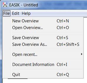
File Menu:
● New Overview
(File | New Overview): Creates a fresh canvas containing no sketches or views.
Any unsaved work will be lost.
● Save Overview
(File | Save Overview): Saves the current overview to an XML file. Note:
overview files are saved with a .easik
extension.
● Open Overview
(File | Open Overview): Opens an overview from a .easik file. Any unsaved work will be lost.

3.1.1.1.1
Edit Menu:
●
Add Sketch (Edit | Add Sketch): Adds a new
empty sketch to the overview canvas.
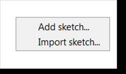
● Import Sketch (Edit | Import Sketch):
●
To
import a sketch (and its views) from an XML file, right click on the overview
and select Import sketch from the
popup menu. (The action is also available through the Edit menu.) Select the
XML file and click OK to add it to the overview.
●
Add View (Edit | Add View): Creates a new
empty View of the
selected sketch.
●
Preferences (Edit | Preferences): Opens the Preferences window.
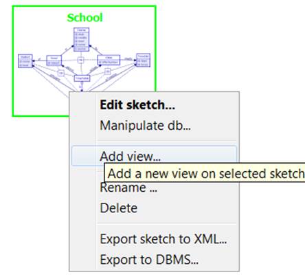
Canvas or Entity Click
● Edit sketch
(Right click on desired sketch → Edit sketch): See Opening a Sketch in Edit Mode
● Manipulate database
(Right click on desired sketch → Manipulate database): See Database
Manipulation.
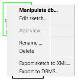
● Export Sketch to XML
(Right click on sketch → Export sketch to XML): See Exporting a
Sketch to XML.
● Export Sketch to DBMS:
See Exporting a Sketch to DBMS
● Add
View (Right click
on sketch → Add view): Creates a new empty View of the selected sketch.
● Rename (Right click on sketch or view
→ Rename): Prompts the user for the new name of the selection.
● Delete (Right click with sketches and/or
views selected → Delete): Deletes the current selection.
● Add Sketch
(Right click → Add sketch): Adds a new empty sketch to the overview
canvas.
● Import Sketch
(Right click → Import sketch): To import a sketch (and its views) from an
XML file, right click on the overview and select Import sketch from the popup menu. (The action is also available
through the Edit menu.) Select the XML file and click OK to add it to the
overview.
3.2 Opening
a Sketch in Edit Mode
To open a sketch for editing, it must exist as a sketch node
in the overview. Right clicking on the sketch node and selecting Edit sketch from the popup menu will
open the sketch for editing. If there is currently no active connection
to an SQL server, a double click will also enter edit-mode. If there is an
active connection to a database, a double-click will
open the sketch in data manipulation mode.
Note:
A sketch cannot be edited if it has been connected
to an SQL server. If the user wishes to make edits to the sketch, they must
first agree
that edits will break the sketch/database synchronization.
3.3 Opening
a Sketch in Data Manipulation Mode
To open a sketch in data manipulation mode, right-click over
the sketch's representation in the overview and select Manipulate database from the popup menu. If a valid SQL connection
currently exists, EASIK
will immediately enter data manipulation mode on the selected sketch. If there
is no such connection, the user is prompted for connection information,
and a connection attempt is made. Should a connection establish successfully,
data manipulation mode will be entered. See database manipulation.
3.4 Opening
a View
From the
overview, a view can be opened to edit by either right
clicking over it and selecting Open
view from the popup menu, or double clicking over it. A view is dependent on the sketch to which it
is connected by an arrow. Therefore the view will be in the same mode
(edit/data manipulation) as the sketch it depends on. If you would like to edit
a view which is currently connected to a database you will have to break the
sync from the sketch before being allowed to enter the view in edit mode. If
you would like to manipulate a view which is in edit mode you will have to
export the sketch and then open the view. See Data Manipulation in a View for available
actions.
4.1
Editing A Sketch
4.1.1
Sketch Editing Actions
This
section outlines the actions available when editing a sketch. (See Editing A
Sketch) Note that any action in a popup menu is also be found in the
EASIK Edit menu. If the action requires information about position on the
sketch (such as adding an entity), a random position is used.
Edit Sketch - Popup Menus
4.1.1.1
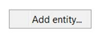
Add
Entity
Right-click at the position on the canvas where the new
entity should be placed. Select Add
entity... from the popup menu.
An entity translates to a table of the database schema.
4.1.1.2
Add
Edge
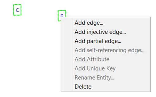
EASIK
supports four types of edges:Normal edges, Injective
edges, Partial
edges, and Self-referencing
partial edges. An edge is represented by a
foreign key in the database schema: an edge from entity A to entity B signifies
that one column of A matches the primary key of B. To
add an edge to the sketch, highlight the desired entities and select Add <edge-type> from the popup
menu. Note that self-referencing edges require only one entity,
while the others require two. A dialog appears prompting for the edge's name
and Edge cascading behaviour.
4.1.1.3
Add
Constraint
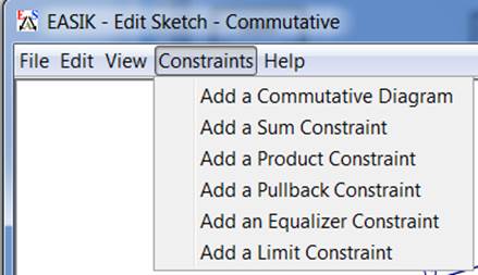
EASIK
supports five types of constraints: Commutative Diagram, Sum Constraint, Product Constraint, Pullback Constraint, and Equalizer Constraint.
Select Add <constraint type>
from the Constraint menu of EASIK
to add the constraint to the sketch. See notes on each constraint type for
details on adding them to a sketch.
4.1.1.4
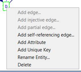
Add
Attribute
Right click on an entity and select Add Attribute from the popup menu. A dialog pops up prompting for
the new attribute's name and Data Type. An attribute corresponds to a column of a table of the database
schema
4.1.1.5
Add
Unique Key
Right
click on an entity that has at least one attribute or at least one
non-injective edge and select Add Unique
Key from the popup menu. A dialog pops up prompting for the key's name,
attributes and edges. Control-click to select multiple attributes/edges.
4.1.1.6
Edit
Attribute
Right click on the attribute in the information tree located
at the right of the sketch window and select Edit Attribute from the popup menu. The selected attribute can then
be renamed, and its type redefined.
4.1.1.7
Rename
Entity
Right
click on an entity and select Rename
Entity from the popup menu. A dialog popup prompting for the entity's new
name.
4.1.1.8
Delete
Right
click with any combination of entities and edges highlighted. Choosing Delete from the popup menu will remove
the highlighted selection from the sketch.
4.1.1.9
Delete
Attribute
Right click on the attribute in the information tree located
at the right of the sketch window and select Delete Attribute from the popup menu. The selected attribute will
then be deleted from its entity.
4.1.1.10
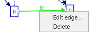
Edit
Edge
Right click on an edge and select Edit edge from the popup menu. A dialog pops up allowing the edge
to be renamed and its cascade behaviour specified.
● Restrict:
Causes attempted deletions of referenced rows to fail.
● Cascade:
Cause deletions in this table to trigger deletions of any rows in other tables
that reference
the row(s) being deleted.
● Set null:
Causes references to be set to NULL when the targeted row is deleted (only
available on partial edges.)
4.1.2
Edge Types
This
section describes the four types of edges available within EASIK. See Add Edge for details
on adding an edge. The edge types are distinguished graphically as seen in the
picture below.
4.1.2.1
Normal
edges
The normal edge type in EASIK is a non-nullable
reference to a row of another entity. This represents a many-to-one
relationship between entities.
4.1.2.2
Injective
edges
Injective edges are non-nullable,
unique references to a row of another entity. Because the reference must be
unique, this represents a one-to-one relationship between entities, and corresponds to the ERA
"is-a" relationships between entities.
4.1.2.3
Partial
edges
Partial edges are like normal edges, but may have null
references; that is, there
may not be a referenced tuple in
the target entity.
4.1.2.4
Self-referencing
partial edges
Self-referencing
edges allow tuples of an entity to refer to other tuples of the same entity.
These edges must be partial: it would not be possible to insert the first tuple
of a table if a null value for the reference value was not permitted.
Self-referencing edges can be useful for representing tree or graph structures
within a database.
4.1.3
Edge warnings
In the
event that adding an edge creates a strongly connected fully defined component
(SCFDC)of the sketch, that is, a portion of the sketch
where every entity can reach every other entity through a non nullable path of edges, the user will be warned. The
warning is used because in a SCFDC it will be impossible to perform an initial
insert. This is because every table needs a non nullable
foreign key to another entity which in turn needs a non nullable
foreign key to the next table, eventually reaching the first table where you
tried to insert.
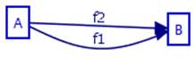
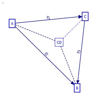
The user
will also be warned if inserting an edge causes the creation of parallel paths,
with at least one path being fully cascade and at least one other path not
being fully cascade. Parallel paths with different deletion policies can cause
unexpected results. For example in the simple diagram below where f1 is on delete cascade and f2 is on delete restrict. Suppose one row has
been created in B and one row, with both foreign keys pointing to the one
available row in B, has been created in A. If the user deletes the row in B
what will happen? The user may expect the row to not be deleted because of the
restrict clause or they may expect the row to delete and then cascade to delete
in A as well. In this case the row cascades and both rows are eliminated.
4.2
Constraints
There are
several EA constraints that can be implemented and represented graphically
using EASIK. These constraints include Commutative Diagram, Sum Constraint, Product Constraint, Pullback Constraint, and Equalizer Constraint.
Defining constraints requires selecting paths in the sketch. This is done by
successive ctrl-clicks on composable edges and then
clicking Next
or Finish as described below. Note:
By definition, some entities involved in constraints have rows that are
automatically generated. EASIK restricts insertion and deletion on such
entities.
4.2.1
Commutative Diagram
A
commutative diagram is a number of paths each of which has the same source
entity and the same target entity. A
commutative diagram constraint is satisfied if, for every row in the table of
the source entity, the value is the same row in the target entity regardless of
which path is followed.
Example
Commutative Diagrams:
To add a commutative diagram constraint, select Add a Commutative Diagram from the Constraints menu.
Select the first path in the commutative diagram. This path
should begin with the source
entity of the commutative diagram and should terminate at the target entity.
Once the path is selected, click Next.
After selecting the first path, the user will then be
prompted to select the second path. Once the second path is selected, the user
may then choose Next
or Finish depending on whether more
paths are involved in the commutative diagram constraint, or whether all paths
are accounted for. The user will continue to be prompted to add more paths to
the commutative diagram until the Finish
or Cancel button is pressed. There is
no upper bound to to the number of paths
in a commutative diagram.
Should the commutative diagram requirements be violated, an
error will be produced and no path will be built.
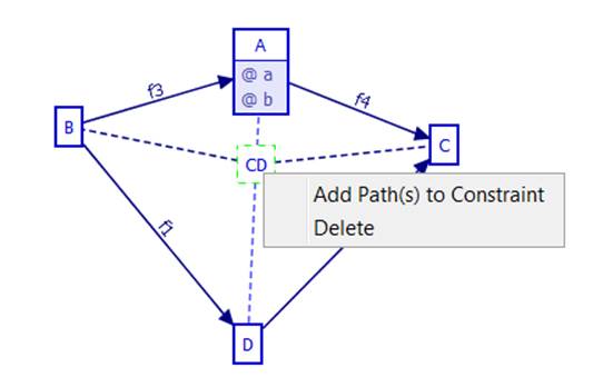
After it is created, new paths can be added to the
constraint by right clicking over it in the sketch and selecting Add path(s) to constraint. Path
selection works as described above.
4.2.2
Sum Constraint
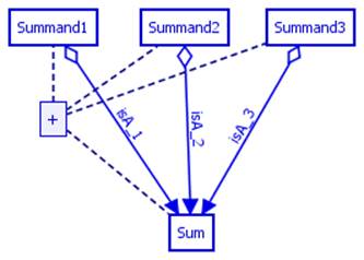
A sum
constraint consists of two or more summand entities, a sum entity and a path
(beginning with an injective edge) from each summand to the sum. The sum constraint is satisfied if the sum
entity rows are isomorphic to the disjoint sum of the rows of the summands.
Example
Sum Constraints:
To add a sum constraint to the sketch, select Add Sum Constraint from the Constraints
menu. Select the first path involved in the constraint. This path should begin
at a summand and end at the sum. Confirm this path by pressing the Next button at the bottom of the window.
After selecting the first path, the user will then be
prompted to select the second path. Once the second path is selected, the user
may then choose Next
or Finish depending on whether or not
more paths are involved in the sum constraint. The user will continue to be
prompted to add more paths until the Finish
or Cancel button is pressed. There is
no upper bound to the
number of paths in
a sum constraint.
There are several conditions that must be observed for the
successful creation of a sum constraint:
● All
paths involved must have
the same target entity
● All
paths involved must have the first edge in the path an injective edge
● At
least two paths must be selected
Should
these conditions not be met, an error message will appear, and the constraint
will not be created.
After it is created, new paths can be added to the
constraint by right clicking over it in the sketch and selecting Add path(s) to constraint. Path
selection works as described above.
4.2.3
Product Constraint
A product
constraint consists of two or more factor entities, a product entity and a path
from each factor to the product. A product constraint is satisfied when the
rows of the product entity are isomorphic to the cross product of the rows of
the other (factor) entities involved in the constraint via the paths from the
product entity to the factors.
Example
Product Constraint:
To add a product constraint to the sketch, select Add Product Constraint from the Constraints menu. The user will then be
prompted to select the first path involved in the constraint, and confirm this
path by pressing the Next button at
the bottom of the window.
After selecting the first path, the user will then be
prompted to select the second path. Once the second path is selected, the user
may then choose Next
or Finish depending on whether or not
more paths are involved.
The user will continue to be prompted to add more paths to the product
constraint until the Finish or Cancel button is pressed. There is no
upper bound to how many paths can be involved in a product constraint.
There are several conditions that must be observed for the
successful addition of a product constraint:
● All
paths must have the same source entity
● At
least two paths must be selected
● All projections must be fully
defined and normal edges
Should
these conditions not be met, an error message will appear.
After it is created, new paths can be added to the
constraint by right clicking over it in the sketch and selecting Add path(s) to constraint. Path
selection works as described above.
4.2.4
Pullback Constraint
A pullback
is very similar to a database join. It requires a two (or more) defining paths with a common
target and two (or more) “projection”
paths with a common source, the pullback entity, one for each defining path and
whose target is the source of the corresponding defining path. A pullback
constraint is satisfied if there is exactly one tuple in the pullback entity
for each list of tuples from the source entities of the defining paths which
are sent to the same value in their common target.
Example
Pullback Constraint (the defining paths are f3 and f4, the pullback entity is A and the projection paths are f1, f2):
To add a pullback constraint to the sketch, select Add a Pullback Constraint from the Constraints menu. The user then defines
the paths involved in the pullback constraint. The paths must be selected in
the correct order.
For a
pullback of width n, the first n paths must
have a common target
- the target
of the pullback. The n+1st
path must have the pullback entity as its source
and its target
must be the source
of the first selected path. The n+2nd path has
the pullback entity as its source
and its target
must be the target
of the second selected path. After
the last
path is selected, click Finish.
There are several conditions that must be observed for the
successful addition of a pullback constraint:
● The
first to nth paths
must have a common target
● The next n
paths must have a common source
and be fully defined
● The
target
of n+1st path
must be the source
of the first; the target
of the n+2nd
path must be the source
of the second and so on
Should
these conditions not be met, an error message will appear, and the constraint
will not be created.
4.2.5
Equalizer Constraint
An
equalizer constraint has an equalizer entity with a path (whose first edge is
injective) to an entity which is the source of two (or more) parallel paths to
a common target. An equalizer constraint is satisfied when the rows of the
equalizer entity are exactly those rows of the source entity of the parallel
paths whose values match under the action of the two (or more) paths to their
common target.
Example
equalizer constraints:
To add an equalizer constraint to the sketch, select Add Equalizer Constraint from the
Constraints menu. The user will then be prompted to select the first path, the
projection, involved
in the constraint. This path must begin with an injective edge that has the
equalizer entity as its source.
Confirm this selection by pressing the Next
button at the bottom of the window.
After selecting the first path, the user will then be
prompted to select the second path. Its source
must be the target
of the first path. A third path with the same source and target as the second path must be
selected, and the user may then choose Next or Finish
depending on whether or not more paths are involved. The user
will continue to be prompted to add more paths to the equalizer constraint
until the Finish or Cancel button is pressed. There is no
upper bound to how many paths can be involved in an equalizer constraint.
There are several conditions that must be observed for the
successful addition of an equalizer constraint:
● The
first path must begin
with an injective edge
● All
paths (excluding the first) have as their source the target entity of the first
edge
● All
paths (excluding the first) must have the same entity as their target
Should
these conditions not be met, an error message will appear, and the constraint
will
not be created.
4.2.6
Adding Paths
Some constraints support path addition after their creation.
These include Commutative Diagram, Sum Constraint, and Product Constraint.
To add one or more paths to a constraint, right click on its entity
and select Add path(s) to constraint
from the popup menu. Paths can then be selected by successive ctrl-clicks on composable edges and clicking either next to select another path, or finish
to add the selected paths to the constraint.
5.1
Database Connection
EASIK
requires an active connection to an SQL server for some functionality, such as
exporting a sketch to database and manipulating a database which is defined by
an EASIK sketch. When EASIK determines that a connection is needed, if a one
has not previously been established, the user has the option to make a connection.
5.1.1
Establishing a connection
1.
Select
an SQL dialect (MySQL).
2.
Select
database parameters.

If
exporting, the user is prompted for database parameters.
3.
Enter
database connection options:
o Username: The username on the database
server.
o Password: <Username>'s password on
the database server.
o Database
hostname: Location
of the database server.
o Database
port: The port on
which to attempt the connection. Defaults are used when this field is left
blank.
o Database
name: The name of
the database that is defined by the current sketch. If exporting the sketch,
this is the name that will be given to the new database. If connecting to a
database, this must be the name with which the sketch had been exported.
o Identifier
quoting: If
enabled, this setting will make EASIK use SQL identifier quoting when
interacting with the database. When enabled, this allows you to use
non-alphanumeric values in entity, edge, and attribute names, which will be
preserved in the generated SQL tables. Note, however, that if quoting is used,
it must be used continually, including other tools accessing the database (for
MySQL, this means using `identifier`).
When
disabled, non-alphanumeric characters will be converted to underscores.
This
setting defaults to off.
Also
note that when an entity or attribute conflicts with a built-in SQL keyword for
the driver being used, quoting of the identifier will be forced, even if this
setting is disabled.
5.2
Sketch Exporting
This
describes the various ways of exporting an EASIK sketch.
5.2.1
Exporting a Sketch to DBMS
This
action is started by right clicking on the desired sketch from the overview and
selecting Export to DBMS from the
popup menu. If there is currently no active connection to a database, the user
is prompted for connection
information and database parameters.
The following is a list of the database parameters.
5.2.1.1.1
Database
Parameters
● Create
database: Set
database definition to create a new database.
● Drop
database before creating:
Available if Create database enabled.
Sets database definition to drop an existing database in the event of a naming
conflict.
● Use
BIGINTs instead of INTs for keys:
Enabling this option changes the type of foreign key columns and the primary key columns to
which they point from the default of int(11) to bigint(20).
Once a
connection is established, the sketch (and its views) are converted to SQL code
and sent to the server. The database is created and the sketch is opened in data manipulation mode.
The user can now interact with the new database. Note that this export action
can also be found in the file menu of the sketch window - File | Export to |
SQL server.
5.2.2
Exporting a Sketch to XML
EASIK can
create an XML file which defines the graphical layout of a sketch and information about
its constraints. This is the file which is loaded when a sketch is imported. To
export a sketch to an XML file, right click on its representation in the overview and
select Export sketch to XML from the
popup menu. The action can also be fired through the menu bar in the sketch
window - File | Export to | XML. Select where the XML is to be saved and click
OK. Note that all views of this sketch are automatically exported. Note also
that these XML files are given a .sketch extension. See Import Sketch for
details on importing.
5.2.3
Exporting a sketch to an SQL Text File
This
provides a text file containing the SQL data definition code sent to the server
by the Export to DBMS action. This export can be selected from the File menu of
the sketch window - File | Export to | SQL text file. The following steps are
then taken to export the sketch to an SQL text file.
1.
Select
SQL dialect (MySQL).
2.
Select
database parameters.
3.
Enter
database connection options
o Database
name: The name
used for the new database.
o Identifier
quoting: See identifier quoting for
details.
4.
Select
where the SQL text file is to be saved and click OK.
5.2.4
Export a Sketch to Image File
This
action can be selected from the File menu in the sketch window - File | Export
to | Image. Select where to save the image file and click OK. The default image
type is png. The image type is specified by including
its extension in the filename. Supported image types are png,
jpeg, gif, and bmp.
5.3
Data Types
EASIK
supports many SQL data types for attributes, and allows you to specify any
additional data type supported by your database. Note that the main data types
listed here may be slightly different, depending on the SQL dialect in use (for
example, the TEXT type becomes a LONGTEXT when exporting to MySQL).
5.3.1
Numeric Types
The
following numeric types are available:
Numeric
Types
● INTEGER: An integer value field (usually a
32-bit int) that stores integer values from
-2147483648 to 2147483647"
● SMALLINT: An integer value field (usually a
16-bit int) that stores integer values from (at
least) -32768 to 32767
● BIGINT: An integer value field (usually a
64-bit int) that stores integer values from
-9223372036854775808 to 9223372036854775807
● DOUBLE
PRECISION: A
floating point value with at least 15 digits of precision (typically a standard
64-bit floating-point value with 53 bits of precision)
● FLOAT: A floating-point value with at
least 6 digits of precision (typically a standard 32-bit floating-point value with
24 bits of precision). This is sometimes known as a REAL, but a REAL is also
sometimes an alias for a DOUBLE PRECISION
● NUMERIC: A fixed-point numeric type. Also
known as DECIMAL. This type is substantially slower than integer and
floating-point types, but guarantees precision for the range of values it
supports. The precision value is the total number of digits storable, and the
scale is the number of digits stored after the decimal point.
"12345.67" has precision 7 and scale 2.
5.3.2
Character/Data Types
The
following character and data types are available:
● VARCHAR(n): Stores a string of characters of
up to size n. Unlike a CHAR, a VARCHAR column is typically stored using the
minimum storage space required, while a CHAR field pads shorter strings to
always store values of size n.
● CHAR(n): Stores a string of characters of
up to size n. Unlike a VARCHAR, a CHAR column is typically padded up to the
specified size to make it a fixed-width column (the padding is removed on
retrieval). Note that some implementations implicitly convert CHAR columns to
VARCHAR if other variable-size columns exist in the table.
● TEXT: Stores large amounts of text
data. Also sometimes known as a CLOB.
● BLOB: Stores large amounts of binary
data (bytes).
5.3.3
Date/Time Types
The
following date/time types are available:
● DATE: A date field that does not
include a time, such as "2008/07/14".
● TIME: A field that stores just a time
(e.g. "12:13:14").
● TIMESTAMP: A field that stores a date and
time (e.g. "2008/07/14 12:13:14"). Note that this is converted to a
DATETIME when using MySQL.
5.3.4
Other Types
The
following other types are supported:
● BOOLEAN: A column that stores true/false
values. Note that this type may be converted to a small integer type by
databases (such as MySQL) that do not fully support BOOLEAN data types.
● Custom
Data Type: This
allows you to specify any data type supported by your database. Note that the
type you enter here will not be checked for correctness: ensure that the provided
type is valid for the SQL type(s) you intend to use.
5.4
Database Manipulation
5.4.1
Setup
In order
to manipulate a database that has been created through EASIK, the following
conditions must be met:
● The sketch that defines the
database must exist as a sketch node in the overview. (See importing/exporting a sketch)
● An active connection to a compatible database on an SQL server
must exist. (See connect to
an SQL database)
By a compatible database, we mean a database
onto which our sketch maps (entities to tables, attributes to columns, edges to
foreign keys, constraints to triggers and unique keys to unique indexes.) There
is currently no utility to automatically detect compatibility between database
and sketch. If an export was triggered from within EASIK and no editing has
been done to the sketch since, we trust that the user has not connected to the
server by other means and altered the database. We therefore assume the
database is compatible. If, however, our sketch has no knowledge of a database
synchronization (e.g. it was created by an EASIK-generated SQL text file), the
user is prompted to verify that they are indeed connecting to an appropriate
database.
5.4.2
Database Manipulation Actions
The
section outlines the actions available by right clicking on an entity while in
a sketch that is open in data manipulation mode. See Data manipulation in Views for additional
information. Note that as mentioned in constraints, insertion and deletion is restricted
on some entities.
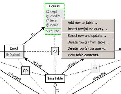
Data
Manipulation Mode - Popup Menus
● Add
Row to table: Adds
a row to the highlighted table. The user specifies values for each column
through a popup dialog.
● Insert
row(s) via query:
Pops up a query dialog from which the user is free to execute any SQL INSERT
query.
● Select
row and update:
The user is prompted to select a row from the highlighted table. A dialog is
then displayed that allows the user to update any of the row's column values.
● Delete
row(s) from table:
The user is prompted to select one or more rows from the highlighted table. The
selected rows are then deleted from the table. Note that cascade behaviour for
affected edges is invoked.
● Delete
row(s) via query:
Pops up a query dialog from which the user is free to execute any SQL DELETE
query. cascade
● View
table contents:
Displays the contents of the highlighted table on the screen.
EASIK
currently supports data manipulation of view nodes and the functionality of
connecting view nodes via edges. Views of a sketch are automatically included
when the sketch is exported to XML or SQL.
A view in
EASIK is simply a collection of query
nodes and edges. A query node is a named node on the view window. It
defines an SQL view via an SQL SELECT query. Edges and constraints are
automatically added in views when the required elements have been queried. For
example, if the sketch contains two node nodes, en1 and en2, and a normal edge,
f1, between them and we have two query nodes in the view, qn1 and qn2, which
query en1 and en2 respectively then f1 will be added to the view automatically. Similarly for constraints, if a commutative
diagram involves four entity nodes and all four are being queried - without
WHERE clauses -- in the view then the
constraint will be added to the view. WHERE clauses in a query node will void
this constraint addition because we will not be able to guarantee constraint
consistency.
6.1
Editing a View
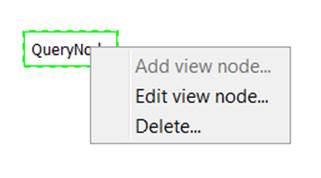
This section outlines the available actions when right
clicking a view node
while the view is opened for editing.
6.1.1
Add View Node
o
The user is prompted for the view
node name. This will become its SQL view name when exported to SQL. The query
entered is an SQL SELECT statement that the view implements.
6.1.2
Edit View Node
o
The user is prompted for a new name
and new SELECT statement for the selected node.
View -
Editing Popup Menu
6.1.3
Delete View Node
o
When selected, a confirmation pop up
is shown. If yes is selected, the view node
is removed from the view as well as any edges that originate at the view node.
6.2
Data Manipulation in a View
For data
manipulation in general see Database
Manipulation
6.3 View
Updatability
A view
query node is updatable if these conditions are met
●
The
entity node it queries is updatable.
○
Entity
nodes may not be insertable if they are part of a
constraint. For example, we cannot directly insert into the target of a sum
●
If
inserting into a query node will cause an insert into another node, or will
require you to choose a row in another node, all these nodes must be queried in
the view for the query node to be updateable.
○
The
entity node being queried has edges going to a target entity node that is not
queried in the view.
○
The
entity node is part of a constraint and inserting into it will cause a trigger
to insert into a node which is not in the view. See constraints and
updatability.
●
The
query node is SELECT * FROM <entity>
6.4
Constraints and Updatability
When a
view node is part of a constraint, inserting into it may cause an insert into
another node in the constraint. In this type of situation we do not allow
updates to that node unless all the nodes into which it may insert are also
queried in the view. The following are all the situations where this occurs.
●
In
a sum constraint inserting into a summand will insert into sum.
●
In
a product constraint inserting into a factor will cause an insert into the
product.
●
In
a pullback constraint inserting into a side node may cause an insert into the
pullback.
●
In
an equalizer constraint inserting into the source node may cause an insert into
the equalizer
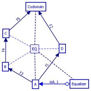
6.5
Updatability and Warnings
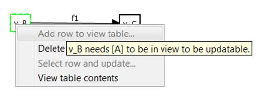
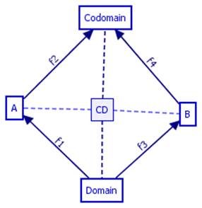
In the
above image we have right clicked on v_B which
queries entity node B which is the source of an equalizer constraint. In this
equalizer constraint A is the equalizer and C is the codomain. C is being
queried by v_C but A is not in the view. We know that
inserting into B may cause an insert into A, and since A is not being queried
in the view, we do not allow an insert. Hovering over the add row to view table
option, which is disabled, gives an appropriate message explaining why it is
disabled.
6.6
Sketch View Synchronization
Sketches
and their Views are synchronized. If an edge is added to a sketch and its
target and source entities are being queried by a view, that edge will also be
added in the view. If it is deleted, it will be deleted from the view. In
EASIK, views are a subsketch of their corresponding
Sketch.
Preferences
are accessed through the Edit → Preferences menu of an overview or
a sketch that is open for editing. (Note: on Mac OS X, the Preferences option
is in the standard location in the main application menu, rather than the Edit
menu).
7.1 General
General preferences control the main EASIK settings.
7.1.1
Path
The path setting defines the default system folder EASIK uses when
opening or saving files. You can set this to be the last folder a file was
opened or saved from ("Last used folder"), the folder EASIK was started
from ("Running directory"), or a specific folder.
The default setting is the last used folder.
7.1.2
Show attributes & unique keys
This option controls whether or not attributes and unique
keys are displayed in new sketches. The default option is enabled. This can be
controlled for a sketch which is open for editing from the sketch window's Edit Menu.
7.1.3
Thumbnail scale
This option controls the size of sketch and view thumbnails
displayed in the overview. A setting of 0.25 means that the thumbnail of
sketches and views will be 1/4
of their actual size; 0.5 would indicate half
of the actual size.
The default setting is 0.25.
7.2 Colours
Colour
settings control the look and feel of EASIK
sketches, views, and the main overview window.
The colours tab allows you to
adjust the colours and, in some cases, line widths,
used within EASIK
for displaying sketches, overviews, and views. To change a colour,
click the Edit button beside the colour you wish to
change. To change a line or border width, drag the slider beside the colour to select the desired width.
7.3
SQL Defaults
The SQL Defaults settings allow you to control the default
settings to be used when connecting to a database, to manipulate
an existing set of tables, or export a sketch to a database.
7.3.1
Default SQL driver
This setting controls the default SQL driver used when
connecting and exporting. Currently, MySQL database connections are supported.
7.3.2
Primary key column names
This
setting controls how the primary key column will be named when exporting a
sketch to an SQL server or an SQL file.
The
default, "id", uses the name "id" for the primary key of
all tables. Alternatively, "<tablename>_id"
can be used to base the primary key column on the table name: for example, the
primary key of the entity "Car" would be "Car_id".
You can also use a custom name; <table> in this custom field will be
replaced with the table name.
7.3.3
Foreign key column names
This
setting controls how foreign keys will be named when exporting a sketch to an
SQL server or SQL file.
The
default, "Use edge labels", will use the label specified for an edge
name in a sketch as the foreign key column. Alternatively, you may use the
target table name followed by the edge label, target table name alone, and
target table name followed by _id name "id" as the foreign key
columns. Note that using a foreign key that does not contain the edge label will not work if there are parallel
edges between entities. You may also specify a custom naming scheme:
<source> will be replaced with the source entity name; <target>
with the target entity name; and <edge> with the edge label.
7.3.4
Identifier quoting
This sets the default enabling of identifier quoting.
7.3.5
Edge cascading
This setting allows you to set the default cascading mode
for edges
(foreign keys). You
can also specify this for an
edge within a sketch.
The two options here are cascading, and restricted.
Cascading deletions means that when deleting a row, any referencing rows will
also be deleted (subject to any foreign keys of the referencing rows).
Restricted disallows any deletion while a row is still referenced. The default EASIK setting is
cascading deletions.
7.3.6
Partial edge cascading
This setting allows you to set the default cascading mode
for partial edges (in SQL, these are nullable foreign
keys). In addition to the two options available for edge cascading,
you may also specify "Set null": this option sets any referring
foreign key values to NULL when deleting a row. The "Set null" option
is the default for partial edges.